帕金斯柴油發(fā)電機(jī)組2806搖桿和搖臂軸組件
帕金斯柴油發(fā)電機(jī)組2806搖桿和搖臂軸組件

Rocker lever and rocker shaft assemblies
To remove and to fit
To remove
Remove the rocker cover, Operation -.
Operation -2
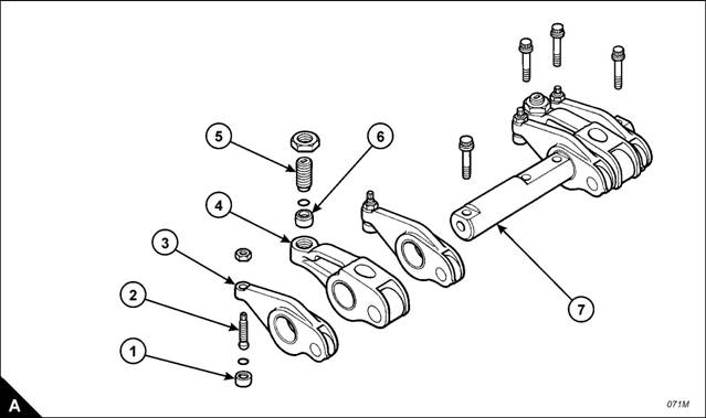
2 The valve rock er levers (A) and the unit injector rocker levers (A2) can move on the shaft (A6) after the four
bolts (A5) have been removed. The shaft (A6) should be kept level when removed from the cylinder head. To
avoid possible personal injury, keep fingers clear of the rocker levers (A and A2) during removal of the
assembly from the cylinder head.
Remove the four bolts (A5).
4 Remove the shaft (A6), valve rocker levers (A) and unit injector rocker levers (A2) as a unit.
5 Repeat steps and 2 for the rocker shaft assemblies which remain.
To fit
Loosen the adjustment screws (A and A4) of each of the rocker levers which have been removed. Install
the rocker shaft assembly in the reverse order to removal.
2 Set the tappet clearances, Operation -4.
Check/adjust the unit injectors, Operation -.
4 Fit the rocker cover, Operation -.

![]()
![]()
2800
To dismantle and to assemble
To dismantle
Note: Check the condition of all components and renew any which are worn or damaged.
Operation -
Slide the valve rocker levers (A) and the unit injector rocker levers (A4) from the s haft (A7).
Note: Fit a new ‘O’ ring seal to any rocker lever adjuster if its button (A) has been removed from the
adjustment s crew (A2).
2 Remove the button (A) from the adjustment screw (A2) in the valve rocker lever (A).
Remove the button (A6) from the adjustment screw (A5) in the unit injector rocker lever (A4).
4 Repeat steps to for the rocker lever assemblies which remain.

![]() 2800
2800
To assemble
Install new ‘O’ ring seals in the buttons (A).
2 Install new ‘O’ ring seals in the buttons (A6).
To fit the ‘O’ ring seals and buttons to the valve rocker levers, proceed as follows:
a. Support the valve rocker lever (A) in a vice which has soft jaws .
b. Put the ‘O’ ring seal and button (A) on the round end of the adjustment screw (A2).
c. Use a soft hammer to seat the button on the adjustment screw.
4 To fit the ‘O’ ring seals and buttons to the unit injector rocker levers, proceed as follows:
a. Support the unit injector rocker lever (A4) in a vice which has soft jaws.
b. Put the ‘O’ ring seal and button (A6) over the end of adjustment screw (A5).
c. Use a soft hammer to seat the button on the adjustment screw.
5 Repeat steps and 4 for the rocker levers whic h remain.
6 Fit the assembled rocker levers to the shafts (A7). Ensure that they are fitted to their original positions.
400-100-8969???15088860848
0574-26871589? 15267810868
0574-26886646? 15706865167
0574-26871569 18658287286


 Deutsch
 Espaol
 Franais
 Italiano
 Português
 日本
日本 韓國
韓國 阿拉伯
阿拉伯 български
 hrvatski
 esky
esky Dansk
Dansk Nederlands
 suomi
suomi Ελληνικ
 印度
印度 norsk
norsk Polski
 Roman
Roman русский
 Svenska
 中文(簡)
中文(簡)